

Section _ Construction and formation of field effect transistors (Mosfet)
The MOSFET field effect transistor is called a "channel" because of its current conduction.
Researcher and author: Dr. ( Afshin Rashid)

![]()
Note: MOSFETs conduct current in their conduction region, which is called the "channel." By applying the appropriate voltage to the gate, this conduction channel can be made larger or smaller. Applying this gate voltage to the transistor will affect the electrical characteristics of the channel and induce an electric field around the gate base. This is why this transistor is called a field effect transistor.
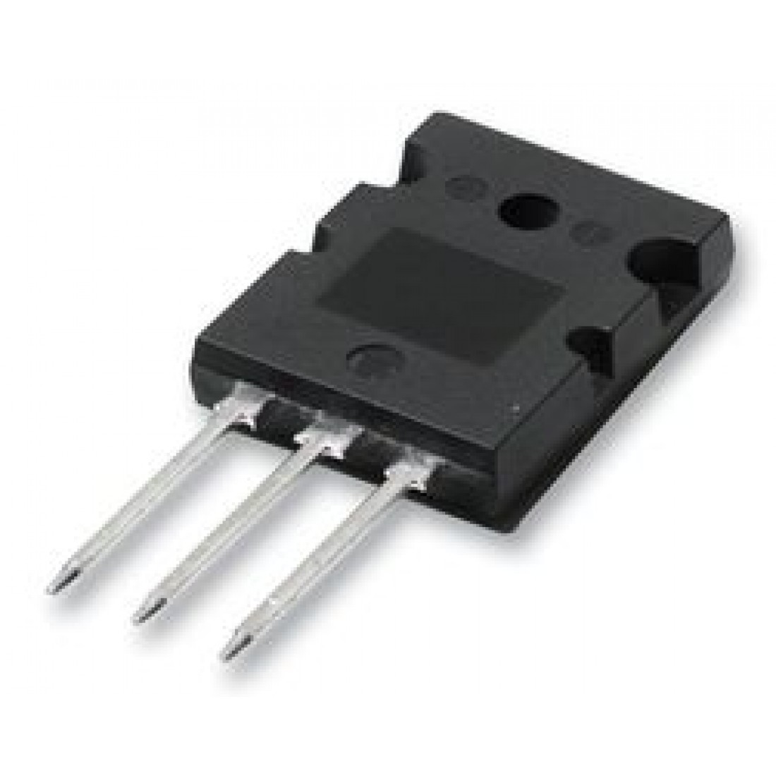
The MOSFET transistor is the core of integrated circuits and because of its very small size it can be designed and manufactured on a single chip. The MOSFET is a four-terminal device with source (S), gate (G), drain (D) and base (B) terminals. The base of the MOSFET is often connected to the source terminal, thus making it a three-terminal device like a field effect transistor. The MOSFET is used in many electronic circuits. It is the most common type of transistor and can be used in both analog and digital circuits. In large circuits, a MOSFET transistor allows us to use a relatively low voltage at the gate to modulate the current from the drain to the source. Two basic types of MOSFETs are used to make discrete circuits.
![]()
A MOSFET is a semiconductor device that is widely used in various electrical and electronic circuits to switch and amplify electronic signals in electronic devices. The Metal Oxide Semiconductor Field Effect Transistor, or MOSFET , is an excellent choice for small-signal linear amplifiers because its input impedance is very high, making it easy to bias. For a MOSFET to have linear amplifying properties, unlike a bipolar transistor, it must operate in the saturation region. However, like a bipolar transistor, it must be biased around a fixed central operating point.

MOSFET Transistor Test
To test the transistor (positive MOSFET), first place the red probe on the source pin, and the black probe on the gate pin. This is to make sure that your transistor is off. Then place the red probe on the source pin, and place the black probe on the drain. In this case, you should be able to see a number on the multimeter. Reverse the probes. (No number will be visible on the multimeter. Now we need to test the transistor in the on state. To turn it on (negative MOSFET transistor), place the black probe on the source pin, and place the red probe on the gate pin. This will turn your transistor on. Now place the multimeter probes on the source and drain pins of the transistor. You should be able to see a number on the multimeter in any direction that you put the multimeter pins on the source and drain.
Researcher and author: Dr. ( Afshin Rashid)
Specialized PhD in Nano-Microelectronics