

Section _ Fabrication and formation of programmable PUT transistors
Programmable Field Effect Transistor ( PUT ) Oscillator Operation
Researcher and author: Dr. ( Afshin Rashid)
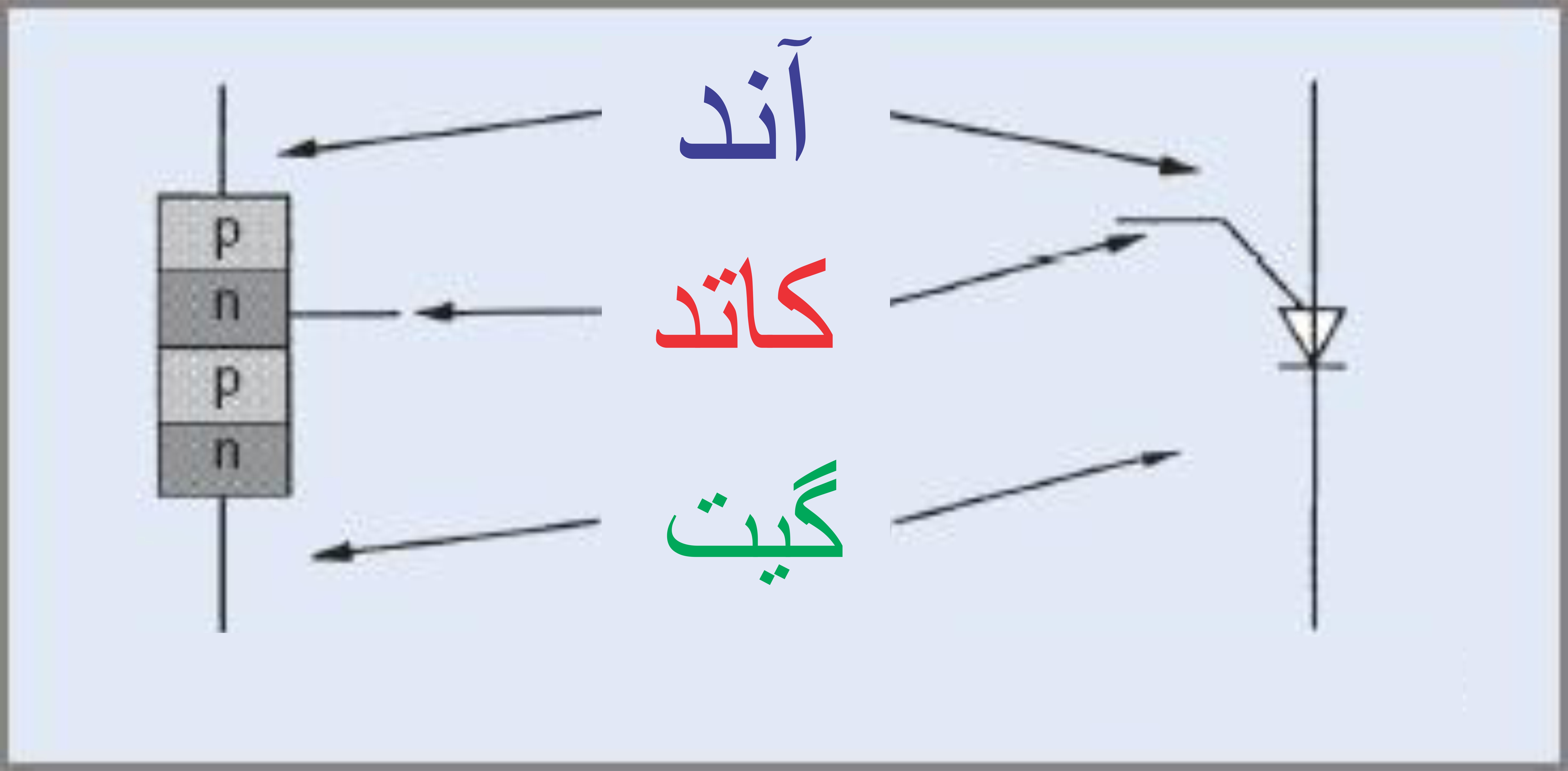
A PUT is similar to a small SCR and works in the same way. It blocks current until it is triggered. When triggered, if the current is high enough, it turns on and stays on until the anode current falls below the holding current. To activate the PUT and put it in the on state, current is transferred from the anode to the gate, so the anode-gate junction must be forward biased, with the anode potential 0.6 volts higher than the gate.

One of the features of the PUT compared to the UJT is that it has a much lower on-state resistance and can carry much higher peak current values. Therefore, it can provide higher levels of trigger energy. The characteristics of the PUT are similar to the UJT , the main differences being that the reverse leakage current (gate to anode) is much lower and the on-state resistance is also much lower.
Programmable single-junction transistor oscillator performance
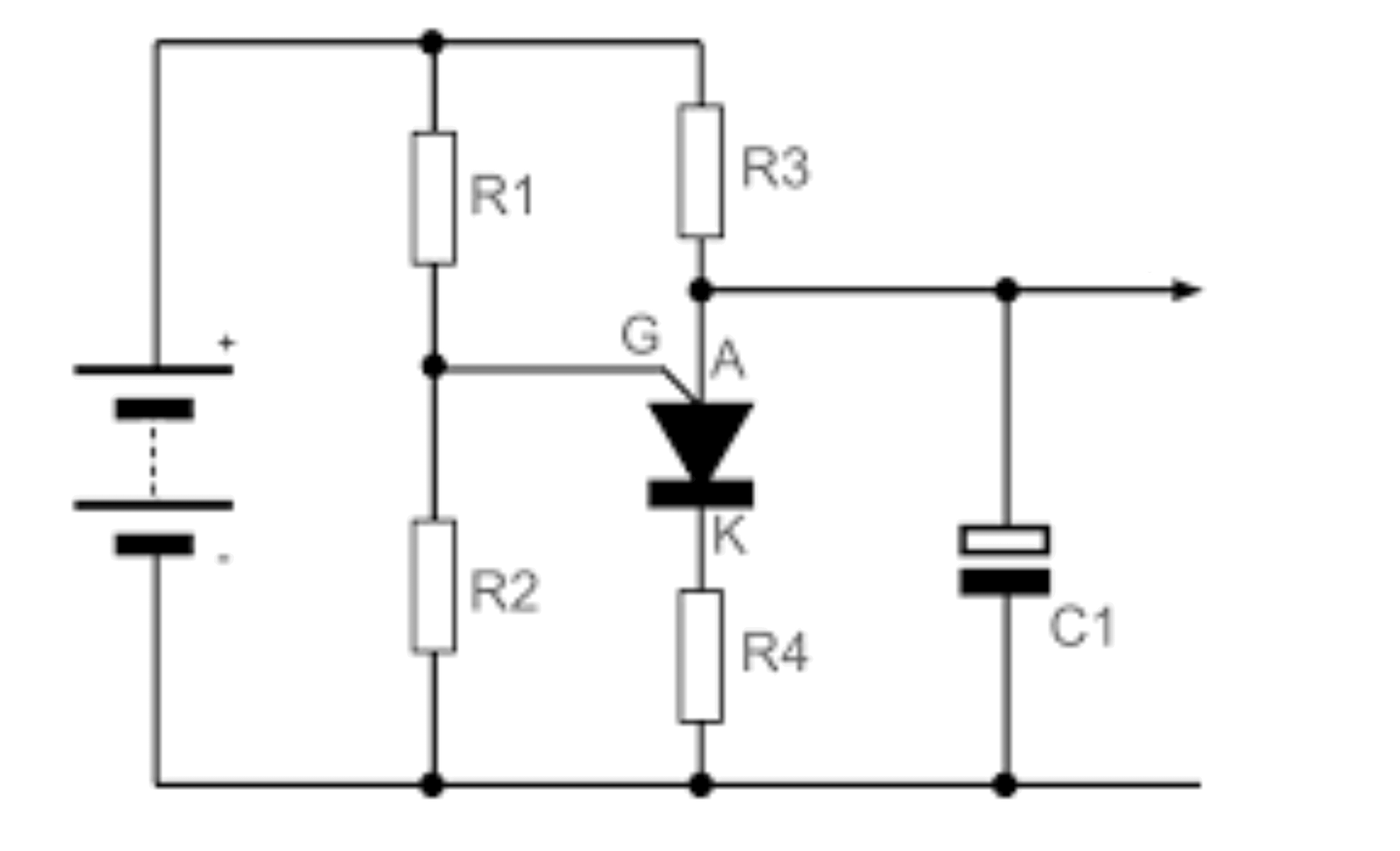
The PUT oscillator operates in a similar manner to the UJT oscillator. Its operation can be summarized as follows:
The resistors create a bias voltage on the gate terminal of the PUT. This voltage depends on the supply voltage and the values of the resistors. These resistors program the gap ratio. When the power supply is connected, the capacitor is charged through the circuit. Its charging rate is determined by the circuit's time constant, or RC. When the anode voltage (voltage across the capacitor) reaches 0.6 volts above the gate voltage, the PUT turns on and latches. When the PUT turns on, the capacitor discharges through the PUT and the resistors . The resistance of this discharge path is very low, so the discharge time is very short. The resulting output pulse will have a high peak value with a very fast rise time, ideal for triggering an SCR or triac. When the capacitor discharges and the cycle resumes, the oscillator returns to the off state. As discussed in the PUT characteristics section , the gate voltage is fixed by the voltage divider and the anode voltage required to turn on the PUT is 0.6 V greater than this voltage. The anode voltage required to turn on the PUT is the peak voltage V P . This value is determined from the following equation.
Researcher and author: Dr. ( Afshin Rashid)
Specialized PhD in Nano-Microelectronics