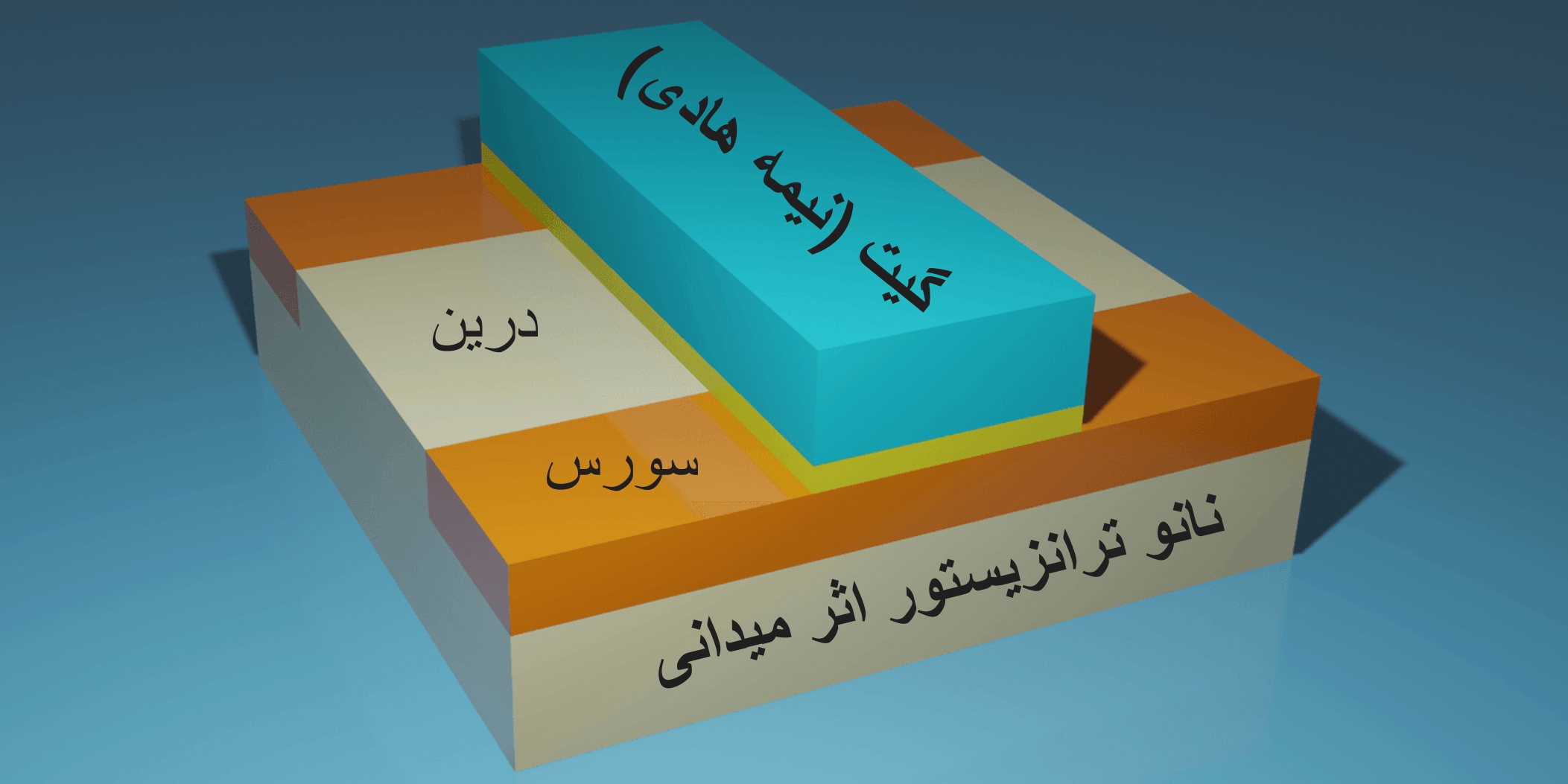
Graphene, which consists of only one carbon atom, can be used to create multilayer graphene field effect nanotransistors that consume less energy and occupy little space.Graphene is a semi-conducting material with zero gap and not suitable for logic circuits, but by using nano technology, they create different forms of this material that have different gaps. Graphene nanoribbons, multilayer graphene and graphene grown on Si are such forms. The term "nano-transistor" comes from the combination of the word "nano-scale" in transmission and resistance. In a Si graphene field effect nano transistor, the resistance between two electrodes can be transferred or controlled by a third electrode. In a Si multilayer graphene field effect nano transistor, the current between the two electrodes is controlled by the electric field from the third electrode. Unlike the bipolar transistor, it is capacitively connected to the third electrode and is not in contact with the semiconductor. Three electrodes are connected to the source, drain and gate in the Si multi-layer graphene field effect nano transistor structure.
مطالب تخصصی و فوق تخصصی (برق _الکترونیک) و (دکترای نانو _ میکرو الکترونیک)
توضیحی کامل درباره مباحث تخصصی و فوق تخصصی برق_الکترونیک و دکترای نانو _ میکرو الکترونیک


________________________________________
🌸🌸 وَ إِن یَکَادُ الَّذِینَ کَفَرُوا لَیُزْلِقُونَکَ بِأَبْصَارِهِمْ لَمَّا سَمِعُوا الذِّکْرَ وَ یَقُولُونَ إِنَّهُ لَمَجْنُونٌ وَ مَا هُوَ إِلَّا ذِکْرٌ لِّلْعَالَمِینَ 🌸🌸 سوره مبارکه قلم ؛ جزء ۲۹ قرآن کریم ؛ آیات ۵۱ و ۵۲
________________________________________
انتشار مطالب فقط با ذکر نام نویسنده بلامانع میباشد(مطالعه تمامی مطالب این وب سایت برای عموم رایگان میباشد.)مطالب آموزشی _ پژوهشی این سایت متنوع و ابتدا در زمینه دکترای نانو و میکرو الکترونیک از زیر مجموعه علوم نانو و برق _الکترونیک میباشد. این سایت برای همه مخاطبان با هر سطح از آشنایی به علوم نانو بیولوژی ، نانو شیمی ، نانو الکترونیک و برق _ الکترونیک میباشد. و علاقه تحقیقی نویسنده بیشتر در زمینه مطالب علوم نانو و میکرو الکترونیک میباشد.
طبقه بندی موضوعی
-
میکرو _نانو الکترونیک(دیوایس ؛ اَفزاره؛ سیستم ؛ اَدوات)
(۶۲) -
دکترای تخصصی نانو _میکرو الکترونیک (آموزشی _ پژوهشی)
(۷۸۹) -
میکرو _ نانو چیپ ها(ریز تراشه) بر پایه دکترای نانو _ میکرو الکترونیک
(۵۶) -
نانو لیزر ها (Nano Laser)
(۴۴) -
نانو مواد ( Nano Materials )
(۶۴) -
نانو شیمی (Nano chemical)
(۱۱۲) -
برق
(۲۲۹)-
📕 برق ساختمان
(۵۷) -
📕 برق ساختمان هوشمند BMS
(۲۷) -
📕 تولید برق پاک(انرژی خورشیدی)
(۴۲) -
📕 برق قدرت
(۴۶) -
📕 PLC (مبانی تا پیشرفته)
(۵۷)
-
-
الکترونیک
(۱۰۸۶)-
📘 الکترونیک(عمومی قطعات _ قطعه شناسی )
(۲۳۴) -
📘 الکترونیک(تخصصی _ فوق تخصصی)
(۲۲۱) -
📘 نحوه تعمیر بُردهای الکترونیکی و (مادر بُرد)
(۲۳) -
📘 مدارهای مجتمع (معرفی انواع ic ها)
(۷۳) -
📘 مدارات منطقی (معرفی گیت های دیجیتال)
(۳۱) -
📘 سنسور ها(الکترونیک)
(۶۸) -
📘 میکروکنترلرها (بانک سِری میکروکنترلرهای مختلف و پرگرامر ها)
(۱۵۴) -
📘 طراحی مدار (الکترونیک)
(۱۲۳) -
📘 پُمپ های الکتریکی (الکترو پُمپ ها) عمومی ؛ صنعتی ؛ چند منظوره
(۳۲) -
📘 موتورهای الکتریکی (عمومی؛ صنعتی ؛ چند منظوره)
(۶۶) -
📘 SMD (الکترونیک نصب سطحی)
(۱۰۴)
-
-
رباتیک و برنامه نویسی
(۲۱۲) -
علوم مخابرات (فرکانس ، رادار ها و سیگنال ها و امواج)
(۱۰۳) -
مبانی برق و الکترونیک
(۱۵۱) -
🔬 نانو بیولوژیک _ الکترونیک
(۷۴) -
💻 نانو حافظه های کوانتومی Nanomolecular memory (نانو الکترونیک)
(۵۶) -
✅ نانو الکترونیک و نانو لوله های کربنی _ گرافنی
(۴۴) -
✴ نانو ترانزیستور ها Nano transistor (نانو _ میکرو الکترونیک)
(۸۰) -
❎ نانو سیم ها (Nano Wire )
(۸۲) -
✳ نانو اَسمبلر ( nano assembler ) رویکردی نوین در علوم نانو الکترونیک
(۵۲) -
ℹ نانو ساختار (Nano structure)
(۸۸) -
💊 نانو بیو الکترونیک (Nano Bio Electronic) بخش نانو حسگر ها
(۴۶) -
☑ نانو الکترونیک (NEMS) مخفف (سیستم های نانو الکتریکی)
(۲۲) -
❇ نانو رُبات های بیو _ الکترونیکی (nano_bots)
(۳۲) -
📁 نانو فولرن و باکی بال ها ( از دیدگاه نانو الکترونیک)
(۳۸) -
🔲 نانو اَدوات الکترونیکی _ نوری Optical nano-electrical devices
(۸۳) -
🔷بسته بندی (مدارات مجتمع SMD) یا ic های کاربردی SMD (شناخت بیش از 100 نوع ic)
(۸۷) -
📡 نانو مخابرات (Nano_telecommunicatison)
(۱۰۱) -
🚦THT (قطعات الکترونیک نصبِ میان سطحی) پایه کوتاه و کج
(۵۵) -
🔎 نانو الکترونیک _ پلاسمونیک
(۸۲) -
DIP (قطعات الکترونیک نصب عُمقی) بُرد های پایه سوراخ دار
(۴۸) -
بُردهای بی مصرف الکترونیکی و بازیابی مدار الکترونیکی(۵۰ نوع مدار الکترونیکی)
(۵۴) -
قطعات الکترونیکی SMT یا (Surface Mount Technology (SMT (مقداری بزرگتر و کشیده تر از smd)
(۴۱) -
💾 حافظه الکترونیکی (الکترونیک و حافظه ها)
(۵۷) -
💥 ترفند تعمیر بُردهای الکترونیکی با سیم کشی شیلد بین قطعات (بُرد الکترونیکی معیوب وجود ندارد)
(۲۴) -
نانو ذرات الکتریکی (نانو الکترونیک)
(۴۴) -
📡 نانو آنتن های اِلکتریکی (مخابراتی)
(۳۸) -
🔵 نانو الکترونیک مولکولی
(۵۱) -
🔴ترانزیستور ماسفِت (Mosfet) ساختمان داخلی و نحوه عملکرد
(۵۱) -
🔷نانو حافظه ها اِلکتریکی و نقاط کوانتومی
(۳۲) -
🔸بخش ( دیود شناسی diode )
(۴۲) -
🔷بخش (خازِن شناسی capacitor)
(۳۶) -
🔺مدار شناسی اِلکترونیک _ تَفسیر ۵۰ نوع مدار الکترونیکی (تخصصی)
(۴۹) -
🔶تولید برق با انرژی هسته ای (ژنراتور ترمواِلکتریک رادیوایزوتوپ)
(۷۷) -
🔻بخش (مقاومت شناسی Resistor)
(۳۴) -
✳ بخش میکرو BGA یا Micro BGA
(۲۴) -
📂 مدار های مجتمع Asic
(۲۸) -
❎ مدارهای مجتمع CPLD
(۲۰) -
💥 _بخش مدار های مجتمع CMD (پایه خرچنگی)
(۲۰) -
🔎 بخش فرآیند (دِشارژ کردن ) برای نانو لوله های الکتریکی
(۶۸) -
💥بخش آزمایشگاه نانو حافظه های اِلکتریکی (Nano Electronic memory)
(۲۸) -
◼بخش (رِگولاتور شناسی Regulator)
(۴۲) -
❎ بخش (آیسی قیری یا آدامسی)
(۲۱) -
🔶بخش «نانو اسپین الکترون ها»
(۵۶) -
🔷بخش نانو سیم های «اِلیگوفنیلین وینیلین» Oligofenylene vanillin
(۴۰) -
🔷بخش مقایسه بین قطعات الکترونیکی DIP و THT
(۳۷) -
✳ آزمایشگاه میکرو الکترونیک FPGA
(۱۹) -
🔸بخش نانو لیزر و الکترونیک
(۴۰) -
🔷نانو اَبَر خازن ها(Nano cloud capacitor)
(۴۲) -
📂 بخش (سِلف _ چوک شناسی) (inductor )
(۳۸) -
🔹شناخت (سوئیچ و کلید های الکترونیکی)
(۳۱) -
💻میکروپروسسورها Microprocessor (ریزپردازنده)
(۳۲) -
🔶سیستم های (نانو و میکرو الکترومکانیکال MEMS)
(۳۸) -
❎ تغییر لیندِمان (change structure) در نانو ساختار های الکتریکی
(۴۴) -
ℹ مدارهای ASIC/FPGA
(۳۸) -
🔸ترانزیستور های nMOS و ترانزیستور های pMOS
(۳۲) -
◼ فیلتر های الکترونیکی کاربردی
(۳۳) -
❎ بخش (ماژول اِلکترونیکی Module) ماژول شناسی
(۷۵) -
🔴بخش نانو _ میکرو آنتن ها و نانو امواج اِلکترومغناطیسی(Nano _ Micro Anntena)
(۳۳) -
🔶 بخش نانو ترانزیستور های اثر میدانی(Nano Teransistor Mosfet)
(۴۳) -
ℹ حافظه (سی _ موس) CMOS
(۳۱) -
📡نانو آنتن های سیستم (رِکتنا Rectenna)
(۲۸) -
✳بخش خازن اِلکترولیتی
(۲۰) -
🔵 مغز (آیسی قیری) Cob ic
(۱۱) -
🔸 نانو فولِرِنس
(۲۴) -
❎ بخش (نانو فولرهای اندوهیستال)
(۱۸) -
💥 نانو ساختارهای اندو هدرال
(۳۲) -
🔬 آزمایشگاه نانو بیو اِلکتریکال (نانو بیوسنسور ها)
(۲۶) -
◼ بخش نانو رآکتور ها و (نانو ساختار ها)
(۷۲) -
ℹ _ بخش باتری ها و پیل های اِلکتریکی
(۲۲) -
🔹 بخش نانو الکترونیک و (امواج پلاسمونیک)
(۲۶) -
☑ فیوز (شناخت فیوز های الکتریکی)
(۲۰) -
🔴 _ بخش آزمایشگاه تکثیر و گسترش نانو چیپ ها
(۴۶) -
🔬 آز مدارهای الکترونیکی
(۴۶) -
❇ بخش الکترونیک و نانو لیزر های صنعتی
(۳۴) -
🔵 ده قانون برای سیم کشی های جامپر
(۱۰) -
🔶 بخش (نانو ساختار خود سازمان دِهی شده)
(۴۴) -
❎ بخش (ترانزیستور های اَثر میدانی)
(۳۳) -
💥 بخش (تکثیر و تولید نانو سیم ها)
(۵۸) -
ℹ بخش فرآیند شبیه سازی در (نانو ذرات الکتریکی)
(۴۹) -
دیود زِنِر (zener diode) _ امنیت در مدار الکترونیکی
(۳۷) -
🔸 نانو الکترونیک و تاثیر محدودیت کوانتومی (Quantum Confinement)
(۲۸) -
🔹 دیود سیگنال «دیود پَسیو شده شیشه ای»
(۲۰) -
✳ بخش دیود وکیوم (Vacuum diode) یا دیود خلاء
(۱۷) -
☑ بخش دیود تونل (Tunnel diode) _ بسیار رسانا و بسیار پر فشار
(۱۵) -
🔴 بخش شناخت از دیود ترایاک (TRIAC)
(۲۲) -
❎ بخش شناخت ترانسفورماتور Transformator
(۲۸) -
🔵 بخش ابزار های نانو بیوسِنسینگ در (نانو الکتریک)
(۳۴) -
❎ بخش _ پین دیود (pin diode)
(۲۱) -
🔸 بخش ترانزیستور تک پیوندی(تَک اتصالی) UJTs
(۲۱) -
💥 بخش ترانزیستور اَثر میدانی ( قابل برنامه ریزی PUT)
(۱۹) -
❎ بخش دیود (آوالانش Avalanche)
(۲۹) -
🔬 نانو سنسور های بیولوژیکی _ الکتریکی (Nano bio sensor)
(۳۰) -
💥 نانو پلاسمونیک و الگوی نانو الکترونیک
(۸۶)
آخرین مطلب
- مدار های مجتمع با (ساختمان گُسسته) منطق گیت (دروازه) برنامه پذیر (منطق CPLD) و (منطق HCPLD) ساختار و عملکرد
- آشنایی بیشتر با منطق (برنامه پذیر) CPLD و HCPLD یا خلاصه شده complex programmable logic device در مدار های مجتمع با (ساختمان گُسسته)
- میکروپروسسور CPLD و HCPLD ( دستگاه منطقی قابل برنامه ریزی پیچیده )
- (مدارهای مجتمع CPLD و HCPLD) بهره گیری از جداول جستجو (LUTs) _ (یک مزیت قابل توجه)
- مدار های مجتمع CPLD و HCPLD با منطق (برنامه پذیر) و (ساختمان گُسسته) از چندین PLD ساده و (SPLD , HPLD) تشکیل شده
- ساختار و معماری HCPLD و CPLD یا خلاصه شده complex programmable logic device در (ریز پردازنده ها و تراشه ها)
- مدار های مجتمع CMD (پایه خرچنگی) از نوع CPLD و HCPLD ( برنامه پذیر )
- ساختار مدارهای مجتمع نوع HCPLD و CPLD (دارای ساختمان گُسسته) _ دارای اتصالات داخلی پیوسته
- بررسی و تحلیل بسته بندی ic های (SMD) از نوع HCPLD
- بررسی مدار های مجتمع CMD (پایه خرچنگی) از نوع HCPLD (ساختمان گُسسته)
پیوندهای روزانه
Field Effect Nano Transistors (Nano Teransistor Mosfet) Circuit diagram of a field effect nano transistor
Field Effect Nano Transistors (Nano Teransistor Mosfet)
Circuit diagram of a field effect nano transistor
Researcher and author: Dr. ( Afshin Rashid)
Note: In the circuit diagram of a multilayer Si graphene field effect nanotransistor, the source and drain electrodes are directly connected to the semiconductor, while the gate electrode is capacitively connected to the semiconductor using the gate dielectric.
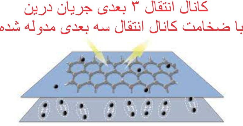
The electric field created by the gate electrode controls the current created by the source and drain electrodes. Drain current transport is modulated by changing the density of charge carriers in the two-dimensional transport channel. In the multi-layer Si graphene field effect nano transistor, a 3D drain current transmission channel is modulated by the thickness of the 3D transmission channel. Many chemical and physical methods have been proposed to produce different types of multilayered nanographene. The basis of the work of physical methods is that in these methods, they try to eliminate the forces between the graphene sheets in graphite and by separating them, they reach single layers of graphene or graphene oxide, which is the same top -down method. Is. In chemical methods, multi-layered nanographene is made by placing individual carbon atoms together, which is also called the bottom-up method.
In the circuit diagram of a multilayer Si graphene field effect nanotransistor, the source and drain electrodes are directly connected to the semiconductor, while the gate electrode is capacitively connected to the semiconductor using a gate dielectric.


